Intermittent Wipers (Part 1)
Many years ago I had to replace the windscreen wiper switch on the Herald, at the time only the two speed ones were available, meaning I had two 'off' positions as the motor is single speed, which was a minor irritation. I had also longed for something a little more than just on or off so I looked at adding an intermittent option. After a little Googling I found what seemed ideal being sold by Maplin, it was under £9.00, so I ordered it.
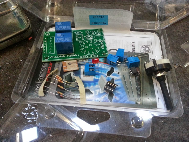
When it arrived I initially thought they'd sent me the wrong thing, but that was because I hadn't read the details properly and it actually arrives in kit form (Pic 1), that's why it was so cheap.....
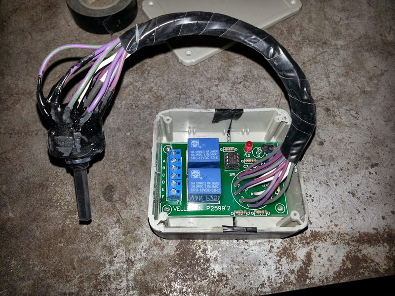
This was my first time soldering together a printed circuit board, but despite the less than clear instructions it went together pretty easily. The timer switch in the kit is meant to be soldered direct to the board, but this would create some issues with mounting it, so I chose to add lengths of cable between the two. If I were to do it again I'd use thinner cable and double the length, as it's 15 cables it becomes quite thick when all together (Pic2).
Once all together you can test to see if it works but running a live feed & earth to it and switch to one of the three 'On' positions. The LED is alight when off, then goes out when the relay switches on, so you can see the time delays before wiring up to your wiper motor.
I fitted the board in a project box, unfortunately there wasn't any the correct size so I chopped an oversize one down a bit. The end result is chunky and ugly, but as it goes up behind the dash it didn't really matter too much.
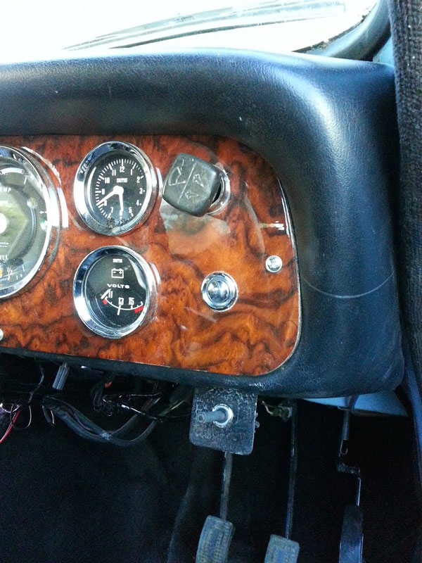
The switch to control the timer I fitted to a temporary home made mount just below the main wiper switch (Pic 3).
The single speed wiper motors fitted to our cars have a constant live and are earthed via the switch on the dash, plus they have a direct earth to allow the motor to park when the earth is broken at the switch when you turn it off.
I wanted to wire the controller so it operated on the vacant 'On' position of the main wiper switch, rather than having to turn on via the switch on the board, I only wanted to touch this when selecting the delay of the wipers. This would mean the main switch operated Off-On Intermittent-On Constant.
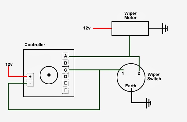
The diagram (Pic 4) shows how this was done initially. The power is a fused 5amp ignition feed, the earth is via the main switch on the previously unused connection, this means the relay on the controller only operates when the switch is at its first 'On' position. The relay switches between connection A & C, so the same earth spurs off and goes in to connection C, out through A and then joins the original earth connection from the motor to the switch.
This worked fine for a couple of days, but then the relay on the board stopped switching. To be honest I was warned by someone else this may happen, as the load from the motor is potentially too great for the on board relay. Kit number two arrived, not wanting to build the whole board again I started swapping the components I suspected as no longer working, after changing the relay to no effect, I swapped an integrated circuit and we were back in business.
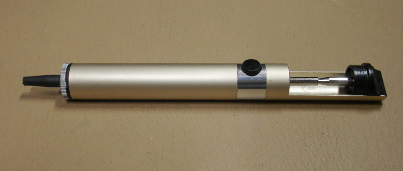
If you've ever wondered how you un-solder something, you can either heat up the solder and use a wick to soak it up or use a sucker (Pic 5). I chose the sucker, £4.00 of EBay and it worked a treat. Just heat up the joint, prime the sucker and place on the molten solder and then push the button, job done.
This time I wired in the controller using a standard 30amp 4-pin relay to carry the load from the motor, that way the relay on the board is just switching the more robust external one. The diagram (Pic 6) shows how this works.

So far this revised wiring arrangement has worked well, time will tell if adding the external relay has made it a reliable modification, but so far I'm very pleased.